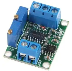
Precíz 24bit-es AD analóg digitál konverter modul, STM32 vezérlővel
ADS1256 24 bit AD high-precision acquisition module, 24 bit ADC, STM32F103C8T6, AD module
Descripton:
Size: 82.8mm, X, 53.4mm
Board thickness: 1.6mm
Size: 82.8mm X 53.4mm
Plate thickness: 1.6mm
Chip model: STM32F103C8T6 (single chip), ADS1256 (24-bit precision AD conversion chip)
Power supply voltage: on-board 5V and 3.3V regulator
components, 9V external DC power
supply can be used, and the power supply has anti-reverse function
Crystal frequency: 8MHZ, 9 times internal frequency of the chip, working frequency 72MHZ
product manual:
1. Power input terminal, input voltage range 5.5V - 12V (5V
power supply, please connect directly to 2);
2. 5V power supply input terminal (1.2 two power supplies, only
one can be connected);
3. STM32F103C8T6 leads GPIO, which is convenient for
secondary development. The silk screen
directly corresponds to the pin number of the chip;
4. Brand new original master MCU: STM32F103C8T6;
5. 2.5V benchmark, ultra-high precision, low temperature drift;
6. Adjustable potentiometer, the output adjustable voltage is
linked to AIN0/ I0;
7. Collect 8 channels of input, I0-I7 is connected to the positive terminal of the acquisition voltage,
G is the analog ground, and the negative terminal of the acquisition voltage is connected;
8. Input filter and attenuation resistor, default is not attenuated, leaving the position of solder
attenuation resistor, 0603 package;
9. ADS1256IDB acquisition chip, new original imported;
10. Power indicator LED;
11. JTAG interface, designed according to JLINK-V8 or V9 definition;
12. STM32F103C8T6 reset button;
13. USB to TTL wiring, corresponding to the MCU's TX, RX, GND, can communicate directly
with the computer;
14. Original imported 3232 serial communication chip;
15. Serial port header, female head;
16. Adjustable potentiometer output voltage to I0 / AIN0 on/off control: Disconnect IO floating,
connect I0 to measure adjustable potentiometer output voltage terminal;
17. STM32 BOOT0 and BOOT1 select control jump caps;
Description:
It is a 24Bit ADS1256 ADC Converter Analog Signal Collector STM32F103C8T6 Controller.
Feature:
1>.ADS1256 24-bit AD High-precision acquistion
2>.Good material durable
3>.Easy to install and use
Parameter:
1>.Chip model: STM32F103C8T6 (microcontroller), ADS1256 (24 bit Precision AD conversion chip)
2>.Power supply voltage: onboard 5V and 3.3V voltage regulator components, 9V external direct Current
powersupply, the power supply has the function of preventing reverse connection
3>.Crystal frequency: 8MHZ, 9 times the frequency inside the chip, working frequency 72MHZ
4>.Work Temperature: -25℃~85℃
5>.Work Humidity: 5%~95%RH
6>.Size:82.8*53.4*1.6mm
Application:
1>.Suitable for collage students, engineers, technicians, factory personal DIY, electronic enthusiasts and
other opertions.
5.8 channel (24 bit) A/DC conversion board hardware features:
1>.This board has led out all the lO ports of the STM32F103C8T6microcontroller, Users can re-develop the
functions they need;
2>.You can download the program through the serial port, see the instruction file for the specific method.
Because it can Download the program through the serial port, so there is no JLINK download and debug
interface on the board;
3>.The reference voltage of the AD chip is 2.5V, which is generated by a precision voltage regulator
device;
4>.There is a potentiometer on the board to test the AD input. This potentiometer is divided by voltage.The
generated voltage is connected to AN0 through the S3 jumper, which is suitable when there is no sensor
Debug
the board under the circumstances. If you don' t need this test, you can take the S3 jumper If the test
voltage is turned off, input the test voltage directly from AN0--AN7. (Input to AD input The voltage of the
terminal cannot be higherthan5V).
Kapcsolódó termékek
Kapcsolódó cikkek
Vélemények (küldje be Ön is véleményét)
Cégünk elektronikai és szoftveres fejlesztésekkel foglalkozik, ami mellett internetes kereskedelmet is indítottunk az ehhez kapcsolódó modulok és fejlesztő egységekkel. Már több mint 15.000 féle termék rendelhető, melyből több mint 5000 saját raktárunkról azonnal elérhető. Fiatal cégként dinamikusan bővülünk, alkalmazkodunk a modern igényekhez. Támogatjuk a hazai fejlesztéseket, és diákokat, termékekkel, szolgáltatásokkal, és saját tudásunkkal. Rendszeres vásárlóink között tudhatunk rengeteg magyar nagyvállalatot, oktatási intézményt, megbízóink között pedig több fejlődő kis- és közép- vállalkozást.
2016-tól mi béreljük az elektrobot.hu-t, mely egy közösségi blog és híroldalként indult, ezen keresztül korábban több elektronikai cég forgalmazott, és jelenleg is hírdeti szolgáltatásait. Rendszeresen jelen vagyunk a magyar elektronikai fórumokon online és kiállítások, rendezvények formájában. Próbáljuk összehozni az oktatásban és versenyeken résztvevőket a fiatal cégekkel, és a komolyabb megbízókkal.


