


\ Loading news...
/
Új vagy? Klikk! Tudtad-e? GYIK Miért mi?

Kijelző, átalakító, mikroproc...
»
Fejlesztő modulok, Arduino, Raspberry
»
Pajzsok - Shield - Arduino - Raspberry Pi
»
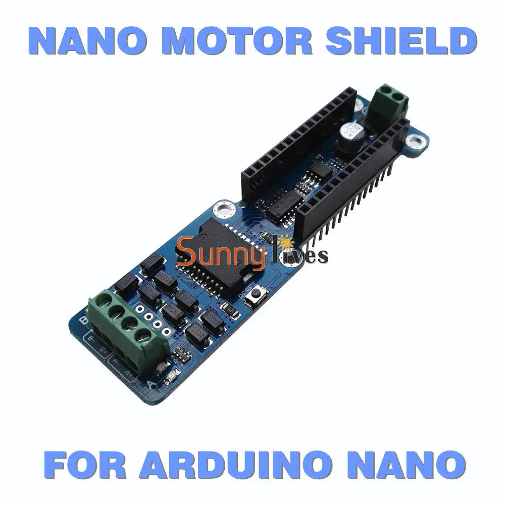


Két csatornás motorvezérlő pajzs Arduino Nano-hoz.
2A csatornánként, 2 teljes H-Bridge meghajtó beépítve, így 2 motort két irányba vezérelhet.
Kiváló pl. kisebb robotokhoz építéséhez
Az Arduino Nano nem tartozék, a képeken csak illusztráció.
The NANO Motor Shield is based on the L298P, which is a dual full-bridge driver designed to drive inductive loads such as relays, solenoids, DC and stepping motors. It lets you drive two DC motors with your Arduino NANO board, controlling the speed and direction of each one independently. You can also measure the motor current absorption of each motor, among other features.
You can find in the Getting Started section all the information you need to configure your board, use the Arduino Software (IDE), and start tinker with coding and electronics.
Technical specs
Operating Voltage:5V to 12V
Motor controller:L298P, Drives 2 DC motors or 1 stepper motor
Max current:2A per channel or 4A max (with external power supply)
Current sensing:1.65V/A
Free running stop and brake function
Power
The NANO Motor Shield must be powered only by an external power supply. Because the L298 IC mounted on the shield has two separate power connections, one for the logic and one for the motor supply driver. The required motor current often exceeds the maximum USB current rating.
External (non-USB) power can come either from an AC-to-DC adapter (wall-wart) or battery. The adapter can be connected by plugging a 2.1mm center-positive plug into the Arduino's board power jack on which the motor shield is mounted or by connecting the wires that lead the power supply to the Vin and GND screw terminals, taking care to respect the polarities.
To avoid possible damage to the Arduino board on which the shield is mounted, we reccomend using an external power supply that provides a voltage between 7 and 12V. If your motor require more than 9V we recommend that you separate the power lines of the shield and the Arduino board on which the shield is mounted. This is possible by cutting the "Vin Connect" jumper placed on the back side of the shield. The absolute limit for the Vin at the screw terminals is 18V.
The shield can supply 2 amperes per channel, for a total of 4 amperes maximum.
Input and Output
This shield has two separate channels, called A and B, that each use 4 of the Arduino pins to drive or sense the motor. In total there are 8 pins in use on this shield. You can use each channel separately to drive two DC motors or combine them to drive one bipolar stepper motor. The shield's pins, divided by channel are shown in the table below:
Functionpins per Ch. A pins per Ch. B
Direction D12 D13
PWM D3 D11
Brake D9 D8
Current Sensing A0 A1
If you don't need the Brake and the Current Sensing and you also need more pins for your application you can disable this features by cutting the respective jumpers on the back side of the shield.
Motors Connection
Brushed DC motor. You can drive two Brushed DC motors by connecting the two wires of each one in the (+) and (-) screw terminals for each channel A and B. In this way you can control its direction by setting HIGH or LOW the DIR A and DIR B pins, you can control the speed by varying the PWM A and PWM B duty cycle values. The Brake A and Brake B pins, if set HIGH, will effectively brake the DC motors rather than let them slow down by cutting the power. You can measure the current going through the DC motor by reading the SNS0 and SNS1 pins. On each channel will be a voltage proportional to the measured current, which can be read as a normal analog input, through the function analogRead() on the analog input A0 and A1. For your convenience it is calibrated to be 3.3V when the channel is delivering its maximum possible current, that is 2A.
The NANO Motor Shield is based on the L298P, which is a dual full-bridge driver designed to drive inductive loads such as relays, solenoids, DC and stepping motors. It lets you drive two DC motors with your for Arduino NANO board, controlling the speed and direction of each one independently. You can also measure the motor current absorption of each motor, among other features.
• You can find in the Getting Started section all the information you need to configure your board, use the for Arduino Software (IDE), and start tinker with coding and electronics.
Technical specs
Operating Voltage 5V to 12V
Motor controller L298P, Drives 2 DC motors or 1 stepper motor
Max current 2A per channel or 4A max (with external power supply)
Current sensing 1.65V/A
Free running stop and brake function
Power
The NANO Motor Shield must be powered only by an external power supply. Because the L298 IC mounted on the shield has two separate power connections, one for the logic and one for the motor supply driver. The required motor current often exceeds the maximum USB current rating.
External (non-USB) power can come either from an AC-to-DC adapter (wall-wart) or battery. The adapter can be connected by plugging a 2.1mm center-positive plug into the for Arduino's board power jack on which the motor shield is mounted or by connecting the wires that lead the power supply to the Vin and GND screw terminals, taking care to respect the polarities.
To avoid possible damage to the for Arduino board on which the shield is mounted, we reccomend using an external power supply that provides a voltage between 7 and 12V. If your motor require more than 9V we recommend that you separate the power lines of the shield and the for Arduino board on which the shield is mounted. This is possible by cutting the "Vin Connect" jumper placed on the back side of the shield. The absolute limit for the Vin at the screw terminals is 18V.
The shield can supply 2 amperes per channel, for a total of 4 amperes maximum.
Input and Output
This shield has two separate channels, called A and B, that each use 4 of the for Arduino pins to drive or sense the motor. In total there are 8 pins in use on this shield. You can use each channel separately to drive two DC motors or combine them to drive one bipolar stepper motor. The shield's pins, divided by channel are shown in the table below:
Function pins per Ch. A pins per Ch. B
Direction D12 D13
PWM D3 D11
Brake D9 D8
Current Sensing A0 A1
If you don't need the Brake and the Current Sensing and you also need more pins for your application you can disable this features by cutting the respective jumpers on the back side of the shield.
Motors Connection
Brushed DC motor. You can drive two Brushed DC motors by connecting the two wires of each one in the (+) and (-) screw terminals for each channel A and B. In this way you can control its direction by setting HIGH or LOW the DIR A and DIR B pins, you can control the speed by varying the PWM A and PWM B duty cycle values. The Brake A and Brake B pins, if set HIGH, will effectively brake the DC motors rather than let them slow down by cutting the power. You can measure the current going through the DC motor by reading the SNS0 and SNS1 pins. On each channel will be a voltage proportional to the measured current, which can be read as a normal analog input, through the function analogRead() on the analog input A0 and A1. For your convenience it is calibrated to be 3.3V when the channel is delivering its maximum possible current, that is 2A.
Kapcsolódó termékek


Kapcsolódó cikkek
Vélemények (küldje be Ön is véleményét)
RÓLUNK
Cégünk elektronikai és szoftveres fejlesztésekkel foglalkozik, ami mellett internetes kereskedelmet is indítottunk az ehhez kapcsolódó modulok és fejlesztő egységekkel. Már több mint 15.000 féle termék rendelhető, melyből több mint 5000 saját raktárunkról azonnal elérhető. Fiatal cégként dinamikusan bővülünk, alkalmazkodunk a modern igényekhez. Támogatjuk a hazai fejlesztéseket, és diákokat, termékekkel, szolgáltatásokkal, és saját tudásunkkal. Rendszeres vásárlóink között tudhatunk rengeteg magyar nagyvállalatot, oktatási intézményt, megbízóink között pedig több fejlődő kis- és közép- vállalkozást.
Cégünk elektronikai és szoftveres fejlesztésekkel foglalkozik, ami mellett internetes kereskedelmet is indítottunk az ehhez kapcsolódó modulok és fejlesztő egységekkel. Már több mint 15.000 féle termék rendelhető, melyből több mint 5000 saját raktárunkról azonnal elérhető. Fiatal cégként dinamikusan bővülünk, alkalmazkodunk a modern igényekhez. Támogatjuk a hazai fejlesztéseket, és diákokat, termékekkel, szolgáltatásokkal, és saját tudásunkkal. Rendszeres vásárlóink között tudhatunk rengeteg magyar nagyvállalatot, oktatási intézményt, megbízóink között pedig több fejlődő kis- és közép- vállalkozást.
KÖZÖSSÉGI JELENLÉT
2016-tól mi béreljük az elektrobot.hu-t, mely egy közösségi blog és híroldalként indult, ezen keresztül korábban több elektronikai cég forgalmazott, és jelenleg is hírdeti szolgáltatásait. Rendszeresen jelen vagyunk a magyar elektronikai fórumokon online és kiállítások, rendezvények formájában. Próbáljuk összehozni az oktatásban és versenyeken résztvevőket a fiatal cégekkel, és a komolyabb megbízókkal.
2016-tól mi béreljük az elektrobot.hu-t, mely egy közösségi blog és híroldalként indult, ezen keresztül korábban több elektronikai cég forgalmazott, és jelenleg is hírdeti szolgáltatásait. Rendszeresen jelen vagyunk a magyar elektronikai fórumokon online és kiállítások, rendezvények formájában. Próbáljuk összehozni az oktatásban és versenyeken résztvevőket a fiatal cégekkel, és a komolyabb megbízókkal.