


Kifejezetten CNC brushless (BLDC kefenélküli) marómotorokhoz is használható fordulatszámszabályzó áramkör. De természetesen feszültségben és áramban megfelelő egyéb kefenélküli motorokhoz is használható.
Alkalmas Hall szenzoros és szenzor nélküli motorok meghajtására is.
Speciálisan 24, 36 vagy 48V-ról szokás táplálni.
Külső potméterről, és külső analóg feszültségről is vezérelhető.
Két típusú motorvezérlő található a szériában, a 180 és 220-as verzió, 12 ill. 14A-rel. Ezeknek az új változatai az "S"-es, ez a vezérlő a WS55-180S
Ajánlás: a 180-as szériát 400W-os motorokhoz, míg a 220-as szériát pl. max 500 és 600W-os marómotorkhoz ajánljuk.
Leírás a WS55-180S és WS55-220SDC vezérlőkhöz:
WS55-180S And WS55-220SDC brushless motor controller, often used24V,36V,48VThree-stage voltage, ranging from20Vreach50VIn this range, the motor can work normally. Compatible square wave with Hall and without Hall, potentiometer speed regulation function, external connection10VVoltage speed regulation function, switch function, speed output function, alarm output function, positive and reverse function, and protective housing.
Widely used in small equipment, electric tools, pumps, fans and other control systems.
Have:
l Start stop
l External potentiometer speed regulation/External voltage regulation
l Inertia stop
l Under voltage protection
l Current limiting
l Over current protection
l Locked rotor protection
l Alarm signal output
l Speed signal output
l Compatible with Hall and Hall-free
Three.Controller performance parameters
Function item | Specifications |
Rated voltage | 20-50VDC |
Rated current | WS55-180S12A WS55-220S14A Note: Controller should be placed in a place with good ventilation and heat dissipation conditions. |
Current limiting | WS55s-180About 13A WS55s-220About 15A Note: Current limiting is to avoid burning down motor and controller under heavy load. In actual use, do not try out and use over rated current. |
Maximum supporting speed | The supporting speed is over 20000RPM, and the specific speed depends on the motor itself and the load. |
Adjust speed | Two speed regulation modes: 1.External potentiometer: speed regulation through this potentiometer; 2.External Voltage: External Voltage10VDCVoltage speed regulation; Note: Two kinds of speed regulation can not be used at the same time. |
Speed output | PGSignal: There is a connection between the port and the ground.5VSpeed pulse output. The output frequency is set toP(HzThe logarithm of motor level isNThe speed isF(RPMThen the output speed frequency is:P=F*N/60; |
Alarm output | ALMSignal: There is an alarm pulse output between the port and the ground. 1.At normal operation, the port output5VHigh level; 2.When the motor is turned on, but the speed regulating signal is very low and the motor is not turning, the port signal is low. Namely: inENWhen the enable key is turned on, as long as the motor does not turn, the alarm port signal is low level, indicating that the current state is abnormal or in doubt, it should be handled. ThreeIn the case of under-voltage, over-voltage, blocking, phase-gap and phase-short circuit, the port signal is low level. |
Positive inversion function | F/RExternal switch, one end of switchF/RPort, one end grounding, switch on and off, motor rotation direction can be changed |
Start stop | ENEnabling key: external switch, one end connectedENPort, one end grounded, switched by switch; motor rotation when connected to ground |
Locked rotor protection | When the motor stops working, the power is restarted. |
Power lamp | Green light: turn on when power is on |
Status light | Red light: When the power is turned on, the potentiometer or the external voltage is not turned on, and in the half standby state, the interval flickers once. Enables not on, standby, spacing flicker seven times |
insulation resistance | > 100M at room temperature and pressure |
Insulation strength | 0.5KV, 1 minute at room temperature and pressure |
Four.Use environment and parameters
Function item | gauge grid | |
Storage temperature | -20C ~ +65 C | |
Use environment | occasion | Avoid direct contact with dust, soot and corrosive gases |
temperature | 0-45Temperature | |
humidity | < 80%No frost, no frost | |
shock | 5.9m/STwoMAX | |
Storage humidity | 0~95%RH | |
volume | 118mm(long)*89mm(Wide, with terminal seat)*33mm(high) | |
weight | 290g(with potentiometers and switches) | |
Five.Terminal wiring mode
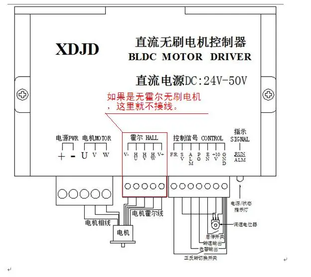
Potentiometer speed regulating wiring mode
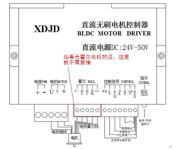
External connection10VSpeed regulating wiring mode
Six.Definition of terminals
Function item | Silkscreen | Function definition |
control signal | F/R | Forward and backward switching interface, the other end connectedGND |
SV | 1.The connection position of the middle terminal of the governor potentiometer is adjusted. 2.External 10V positive connection position, speed regulation; | |
ALM | The alarm signal interface is connected with GND at the other end. | |
PG | Speed signal interface and GND at the other end | |
EN | Switch interface, the other end connectedGND | |
10V | Control signal power supply10V | |
GND | Ground wire | |
Holzer terminal | V-, HU, HV, HW, V+ | Hall signal of motor. To accurately put the controller terminal andCorrect connection with the corresponding line of the motor will lead to abnormal operation of the motor, wrong connection of the power supply and even damage the controller and motor. Hall signal power supply shall not be used for other purposes than those described in the instructions. |
Motor terminals | U, V, W | Connect with motor wire.The incorrect connection will lead to abnormal operation of the motor, and even damage the controller and motor. |
DCinput | + | DCInput terminal |
- | Ground wire | |
Indicator light | RUN/ALM | 1.Green lamp power supply lamp: power is on; 2.Red status lights: standby and semi-standby, flashing1Secondary sum7Secondly, when there are some faults such as blocking, missing phase, short circuit of phase line, etc.LEDFrequent Bright and Other Scintillation Numbers |
Seven.Functions and instructions
l Speed regulation mode (SV)
1. External potentiometer speed regulationThe two fixed ends of the potentiometer are connected to the controller "control" separately."Terminal "+10V"And"GNDConnect the adjusting end to the uuuuuuuuuuuuSVIt is suggested that the resistance of potentiometer should be at10K- 100K
2. External power supply timingConnect the negative pole of the external power supply to the uuuuuuuuuuuGNDThe positive pole receives the uuuuuuuuuuuuSV"Voltage is10V;
l Positive motor/Inversion control (F/R)
The direction of the motor is controlled by switching the forward and reverse switches.
l Turn on and off.EN)
By controlling the terminal.EN"And"GNDThe on-off and off of the motor can control the brake stop of the motor.
l Alarm failure (ALM)
In the following circumstancesALMOutput will follow5V
Kapcsolódó termékek


Kapcsolódó cikkek
Vélemények (küldje be Ön is véleményét)
Cégünk elektronikai és szoftveres fejlesztésekkel foglalkozik, ami mellett internetes kereskedelmet is indítottunk az ehhez kapcsolódó modulok és fejlesztő egységekkel. Már több mint 15.000 féle termék rendelhető, melyből több mint 5000 saját raktárunkról azonnal elérhető. Fiatal cégként dinamikusan bővülünk, alkalmazkodunk a modern igényekhez. Támogatjuk a hazai fejlesztéseket, és diákokat, termékekkel, szolgáltatásokkal, és saját tudásunkkal. Rendszeres vásárlóink között tudhatunk rengeteg magyar nagyvállalatot, oktatási intézményt, megbízóink között pedig több fejlődő kis- és közép- vállalkozást.
2016-tól mi béreljük az elektrobot.hu-t, mely egy közösségi blog és híroldalként indult, ezen keresztül korábban több elektronikai cég forgalmazott, és jelenleg is hírdeti szolgáltatásait. Rendszeresen jelen vagyunk a magyar elektronikai fórumokon online és kiállítások, rendezvények formájában. Próbáljuk összehozni az oktatásban és versenyeken résztvevőket a fiatal cégekkel, és a komolyabb megbízókkal.