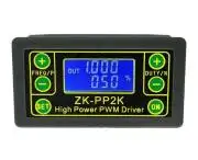
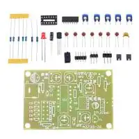
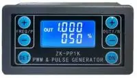
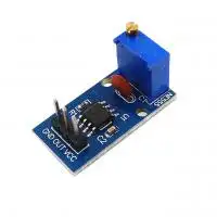
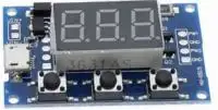
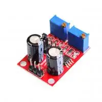
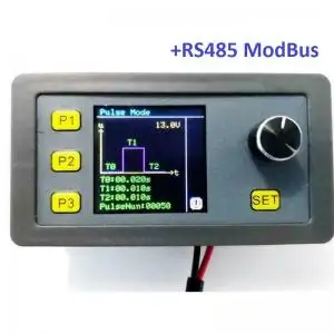
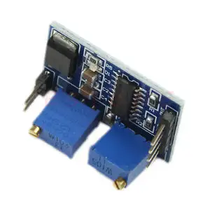
PWM jel generátór, négyszög jel generátor. PWM mód: Beállítható frekvencia és kitöltési tényező is Négyszög jel generátor mód: beállítható késleltetés, magas és alacsony jelszint idő és a ciklusok száma Motor meghajtásra is használható közvetlenül, max 8A mosfetes kimenet. Beállítások részletes leírása az angol részben megtalálható, példákkal együtt. Működési feszültség: 3.3~30V, így széles tartományban használható, a kimeneti jel feszültsége megegyezik a tápfeszültséggel. PWM Generator & Pulse Generator Frequency Duty Cycle Adjustable PWM Driver with Shell ZK-PP2K  Attention: High-power PWM driver (models with suffixes PP2/ PP2K) has no waveform without a load. There is a waveform only after connecting to a load. Internal schematic is shown below:  Applications: 1. Adjust LED brightness, frequency and duty cycle. 2. Adjust motor speed, frequency and duty cycle. 3. Drive solenoid valve to close and release. Automatic loop, delay output, number of loops (or infinite loop) can be set. 4. Turn on and off control equipment, do switch fatigue test, voltage drop and other tests to verify the reliability of customer equipment. 5. Delay start load, delay time can be set. Always on or intermittent work after the delay. Features: - Can directly drive LEDs, motors, solenoids and other loads. - Two modes can be selected: PWM mode: frequency (continuous), duty cycle. Attention: The number of pulses cannot be set in this mode, the module will always send pulses. PULSE mode: positive pulse width time, negative pulse width time, power-on delay start time, and switching times are adjustable. - With start and stop button to control the output and stop of signals. - Wide voltage input 3.3-30V, with 5.08mm wiring terminal. Technical Parameters: - Working voltage: 3.3~30V (Reverse connection is not allowed) - Frequency range: 1Hz~150KHz, accuracy about 2%. Motor speed is generally selected 20KHZ. - Duty cycle range: 0-100%, 1% stepping - Number of pulses: 1-9999, or infinite (---- displayed stands for infinity) - Delay output time: 0.000s-9999s. The minimum can be set 1ms - Positive and negative pulse width length: 0.000s-9999s. The minimum can be set 1ms - Signal loading capacity: less than 8A (MOS switch tube) - Output amplitude: amplitude is equal to supply voltage (OUT+ is directly connected to V+ inside the module)   Module Introduction: 1.Operation Via Buttons:  2. PWM Mode (display with % for PWM mode) Default mode is PWM mode. Set frequency through buttons FREQ+ and FREQ-. Set duty cycle via buttons DUTY+ and DUTY-. Short press button STOP to control signals' output or stop. Output is 0 when stopped. When OUT is displayed on the screen, the module has output. Otherwise, the output is stopped. Default frequency is 1KHZ and duty cycle is 50%. If you need to switch to PULSE mode, press and hold button SET (more than 6 seconds). Do not release it, you will see the screen change and % disappear. Now the module is in PULSE mode. 3. PULSE Mode (No % on the right side of the display is PULSE mode) By buttons P + and P-, you can set positive pulse width time which is displayed in the top line in LCD screen. Press N + and N- buttons to set negative pulse width time, which will be displayed in the lower line in LCD screen, with unit in seconds. Short press button STOP to control signal to output or stop. Output is 0 when stopped. The module has output when the screen displays OUT. Otherwise, output is stopped. Default positive pulse width is 0.5 seconds, and negative pulse width is 0.5 seconds. Setting of pulse number and delay time: In PULSE mode, long press button SET for 2 seconds, then release it to enter pulse number and delay time setting interface. The screen displays SET. After entering the interface, output pulse will be turned off and cleared. Set delay time by pressing buttons P + and P-. Set the number of pulses by pressing buttons N + and N-. Default delay time is 0 seconds and default number of pulses is infinite (display ----). Press and hold SET button for 2 seconds, the module will automatically return to pulse interface. Press button STOP. After delay setting time is completed, the set number of pulses will be sent. After sending the pulse number, the module will output 0 automatically. If the period is not completed, press STOP button to turn off and clear output pulse. The number of pulses set will be sent every time it is started. Application Operation Examples: 1. PWM output 20KHZ, 60% duty cycle: Select PWM mode, set frequency to 20.00 and duty cycle to 060%. 2.Turn on output end for 0.6 seconds and turn off for 0.2 seconds, infinite loop: select PULSE mode, set positive pulse width to 0.600, set negative pulse width to 0.200, set delay time to 0.000, and set the number of pulses to ----. 3.Power on or press SET/STOP button, delay for 5 seconds, then turn on output end for 0.6 seconds, turn off output end for 0.2 seconds, infinite loop: select PULSE mode, set positive pulse width to 0.600, set negative pulse width to 0.200, set delay time to 5.000, and the number of pulses is set to ----. 4. Power on or press SET/STOP button, delay 5 seconds, and then output 100 pulses with high level 10ms and low level 10ms: Select PULSE mode, set positive pulse width to 0.010, set negative pulse width to 0.010, and set delay time to 5.000 and the number of pulses is set to 0100. 5. After power on, delay for 10 seconds, and then output signals permanently: Select PULSE mode and set positive pulse width to a number greater than 0. Set positive pulse width to a number greater than 0 and negative pulse width to 0, set delay time to 10.00 seconds, and the number of pulses to infinite (----). 6.Other applications can explore by yourselves or consult customer service. 7.All setting parameters will not be lost after shutdown. |
Kapcsolódó termékek
Kapcsolódó cikkek
Vélemények (küldje be Ön is véleményét)
RÓLUNK
Cégünk elektronikai és szoftveres fejlesztésekkel foglalkozik, ami mellett internetes kereskedelmet is indítottunk az ehhez kapcsolódó modulok és fejlesztő egységekkel. Már több mint 15.000 féle termék rendelhető, melyből több mint 5000 saját raktárunkról azonnal elérhető. Fiatal cégként dinamikusan bővülünk, alkalmazkodunk a modern igényekhez. Támogatjuk a hazai fejlesztéseket, és diákokat, termékekkel, szolgáltatásokkal, és saját tudásunkkal. Rendszeres vásárlóink között tudhatunk rengeteg magyar nagyvállalatot, oktatási intézményt, megbízóink között pedig több fejlődő kis- és közép- vállalkozást.
Cégünk elektronikai és szoftveres fejlesztésekkel foglalkozik, ami mellett internetes kereskedelmet is indítottunk az ehhez kapcsolódó modulok és fejlesztő egységekkel. Már több mint 15.000 féle termék rendelhető, melyből több mint 5000 saját raktárunkról azonnal elérhető. Fiatal cégként dinamikusan bővülünk, alkalmazkodunk a modern igényekhez. Támogatjuk a hazai fejlesztéseket, és diákokat, termékekkel, szolgáltatásokkal, és saját tudásunkkal. Rendszeres vásárlóink között tudhatunk rengeteg magyar nagyvállalatot, oktatási intézményt, megbízóink között pedig több fejlődő kis- és közép- vállalkozást.
KÖZÖSSÉGI JELENLÉT
2016-tól mi béreljük az elektrobot.hu-t, mely egy közösségi blog és híroldalként indult, ezen keresztül korábban több elektronikai cég forgalmazott, és jelenleg is hírdeti szolgáltatásait. Rendszeresen jelen vagyunk a magyar elektronikai fórumokon online és kiállítások, rendezvények formájában. Próbáljuk összehozni az oktatásban és versenyeken résztvevőket a fiatal cégekkel, és a komolyabb megbízókkal.
2016-tól mi béreljük az elektrobot.hu-t, mely egy közösségi blog és híroldalként indult, ezen keresztül korábban több elektronikai cég forgalmazott, és jelenleg is hírdeti szolgáltatásait. Rendszeresen jelen vagyunk a magyar elektronikai fórumokon online és kiállítások, rendezvények formájában. Próbáljuk összehozni az oktatásban és versenyeken résztvevőket a fiatal cégekkel, és a komolyabb megbízókkal.


