Motor és meghajtó elektronika
»
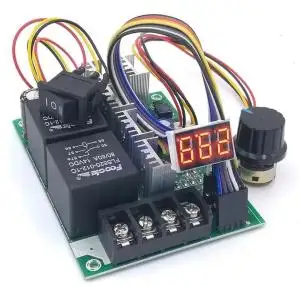
DC Motorvezérlő PWM áramkörök, kézi, H-Bridge
»
Motorvezérlők, DC, PWM, H-Híd, H-Bridge
»
Tápfeszültség (bemenet): 10-60V
Állítható áramkorláttal: 0-20A
Lágyindító funkcióval (soft start)
Bekötés:
M+: Motor pozitív
M-: motor negatíve
Vezérlési lehetőségek (A vezérlési módok és beállításaik jumperrel állíthatóak):
1. Potméteres vezérlés (a beépített 0-5V-os tartományban)
2. PWM külső vezérlés (external jelfeszltség 3-20V lehet, minimum 2mA terhelhetőséggel)
3. Analóg külső vezérlés választhatóan 0-5V vagy 0-10V jelszinttel
Alkalmas egyirányú és két irányú vezérlésre is potméterrel, vagy külső analóg feszültséggel. Utóbbi esetben potméterrel, vagy külsőjellel 0-2.5V-ig egyik irány, 2.5-5V-ig másik irány vezérelhető. STOP mód közép állapotban kb. 2.4-2.6V-ig.
Méret: 9.5cm x: 7cm x 3.5cm , kábehossz 40cm
Features:VCC positive supply 10-60V, be sure to set before energizing voltage adaptation
GND Negative , if you want to reduce the external interference shielding box connected to terminals or here at the cathode connected to the power supply
Connection:
M+ Motor positive
M- motor negative
Control ports:
1. 5V: driver board internal 5V power supply, the output capacity of less than 100mA, with potentiometer mode is recommended only to use , do not drive other circuits
2. PWM: external PWM control signal input level range ,3-20V , 2mA current requirements ;
3. ADJ: external 0-5V or 0-10V control signal input
Connections:
GND: ground control signals , such as the shield shell is not allowed to pick pick here is also not allowed in this place other circuits connected GND,
DOWN: control signal, the internal coupler control signal and GND effective turn ( optocoupler turns on, can also be used microcontroller , NPN switch control )
UP: control signal, the internal coupler control signal and GND effective turn ( optocoupler turns on, can also be used microcontroller , NPN switch control )
STOP: control signal, the internal coupler control signal and GND effective turn ( optocoupler turns on, can also be used microcontroller , NPN switch control )
Mode setting (jumper):
1, M1 = short, M2 = open circuit mode 1; potentiometer voltage three-stage control + STOP allowed to run
(The default value for this speed mode)
STOP LOW can control the motor,
After the input voltage of 2.5V, the motor stops; Usually this range 2.4-2.6, for interference.
2.5 gradually accelerated to 0V reverse rotation,2.5-5V forward speed rotation; That middle position potentiometer stops on both sides of adjustment on both sides of the motor speed.
2, M1 = open, M2 = short circuit, Mode 2; potentiometer voltage + DOWN state control Reversible, STOP allowed to run
STOP low (short circuit to GND on) is enabled, the driver can control the motor voltage and DOWNsignals; high motor brake stops, the voltage and DOWN signal is inactive.
DOWN HIGH forward and low reverse;
ADJ :0-5V input voltage signal corresponding to 0-100% RPM rotational speed, direction depends on the DOWN state.
3, M1 = short, M2 = short circuit, mode 3; pure button (switching signal) control
Lead out four lines, as then three buttons . Or and 5V microcontroller interface driver , MCU sends a low pulse more than 100 milliseconds . Drive current is 5 mA current required to drop .
Press the STOP / DIR: whatever status, speed, motor brake immediately stops ;
Press UP: positive direction accelerate a file.
Press DOWN: reverse direction acceleration a file
Forward and reverse direction acceleration has 10 stalls, such as the current 3 files running in the opposite direction , according to a UP, running into the opposite direction two files ; if the current in the positive direction of the four files , press UP to positive direction 5 file , if the current in the positive direction 3 files, press 5 times DOWN 2 files into the opposite direction
4, PWM frequency setting :
Freq1 = short , Freq2 = short circuit , low frequency ; 5K
Freq1 = open , Freq2 = short circuit, IF ; 10K
Freq1 = short , Freq2 = open circuit , high frequency ; 15K ( the default value for this frequency )
5, 5V/10V control options:
5V/10V = short circuit , 10V signal control ;
5V/10V = open , 5V signal control ; ( default value is 0-5V)
6, S_PWM external PWM signal control :
S_PWM = short circuit, select the external PWM signal to control
S_PWM = open circuit voltage signal signal control
Select the external PWM signal control is not allowed while the input voltage signal, nor can 5V/10V = short circuit.
7, 12V_SEL voltage adaptation ( must be carefully checked before energizing to prevent burn ! )
12V_SEL = short circuit, voltage range 10-18V
12V_SEL = open circuit, voltage range 18-60V ( default value for this voltage )
Voltage adaptation is configured correctly premise : the voltage more than 60V, the more easily damaged ; voltage lower than 10V, the system undervoltage protection
8, overcurrent Recovery:
Mode 3 : Re- ended signal to a STOP to unprotect
Mode 2: STOP signal is reset , that is reconnected after disconnection and GND
Mode 1: STOP signal is reset , that is reconnected after disconnection and GND
9, soft start settings:
WR1: motor speed change rate ( soft-start ) clockwise to increase the time , counter-clockwise to reduce the range of about 0-5 seconds. ( Default 2.5 seconds )
10, the current valve setting:
WR2: current protection value adjustment clockwise to decrease , counterclockwise increases ,0-20A. (Default 15A)
Size:
Length: 9.5cm width: 7cm height: 3.5cm Length of line: 40cm
Kapcsolódó termékek
Kapcsolódó cikkek
Vélemények (küldje be Ön is véleményét)
RÓLUNK
Cégünk elektronikai és szoftveres fejlesztésekkel foglalkozik, ami mellett internetes kereskedelmet is indítottunk az ehhez kapcsolódó modulok és fejlesztő egységekkel. Már több mint 15.000 féle termék rendelhető, melyből több mint 5000 saját raktárunkról azonnal elérhető. Fiatal cégként dinamikusan bővülünk, alkalmazkodunk a modern igényekhez. Támogatjuk a hazai fejlesztéseket, és diákokat, termékekkel, szolgáltatásokkal, és saját tudásunkkal. Rendszeres vásárlóink között tudhatunk rengeteg magyar nagyvállalatot, oktatási intézményt, megbízóink között pedig több fejlődő kis- és közép- vállalkozást.
Cégünk elektronikai és szoftveres fejlesztésekkel foglalkozik, ami mellett internetes kereskedelmet is indítottunk az ehhez kapcsolódó modulok és fejlesztő egységekkel. Már több mint 15.000 féle termék rendelhető, melyből több mint 5000 saját raktárunkról azonnal elérhető. Fiatal cégként dinamikusan bővülünk, alkalmazkodunk a modern igényekhez. Támogatjuk a hazai fejlesztéseket, és diákokat, termékekkel, szolgáltatásokkal, és saját tudásunkkal. Rendszeres vásárlóink között tudhatunk rengeteg magyar nagyvállalatot, oktatási intézményt, megbízóink között pedig több fejlődő kis- és közép- vállalkozást.
KÖZÖSSÉGI JELENLÉT
2016-tól mi béreljük az elektrobot.hu-t, mely egy közösségi blog és híroldalként indult, ezen keresztül korábban több elektronikai cég forgalmazott, és jelenleg is hírdeti szolgáltatásait. Rendszeresen jelen vagyunk a magyar elektronikai fórumokon online és kiállítások, rendezvények formájában. Próbáljuk összehozni az oktatásban és versenyeken résztvevőket a fiatal cégekkel, és a komolyabb megbízókkal.
2016-tól mi béreljük az elektrobot.hu-t, mely egy közösségi blog és híroldalként indult, ezen keresztül korábban több elektronikai cég forgalmazott, és jelenleg is hírdeti szolgáltatásait. Rendszeresen jelen vagyunk a magyar elektronikai fórumokon online és kiállítások, rendezvények formájában. Próbáljuk összehozni az oktatásban és versenyeken résztvevőket a fiatal cégekkel, és a komolyabb megbízókkal.


